Lab alignment procedure: Difference between revisions
No edit summary |
No edit summary |
||
| Line 44: | Line 44: | ||
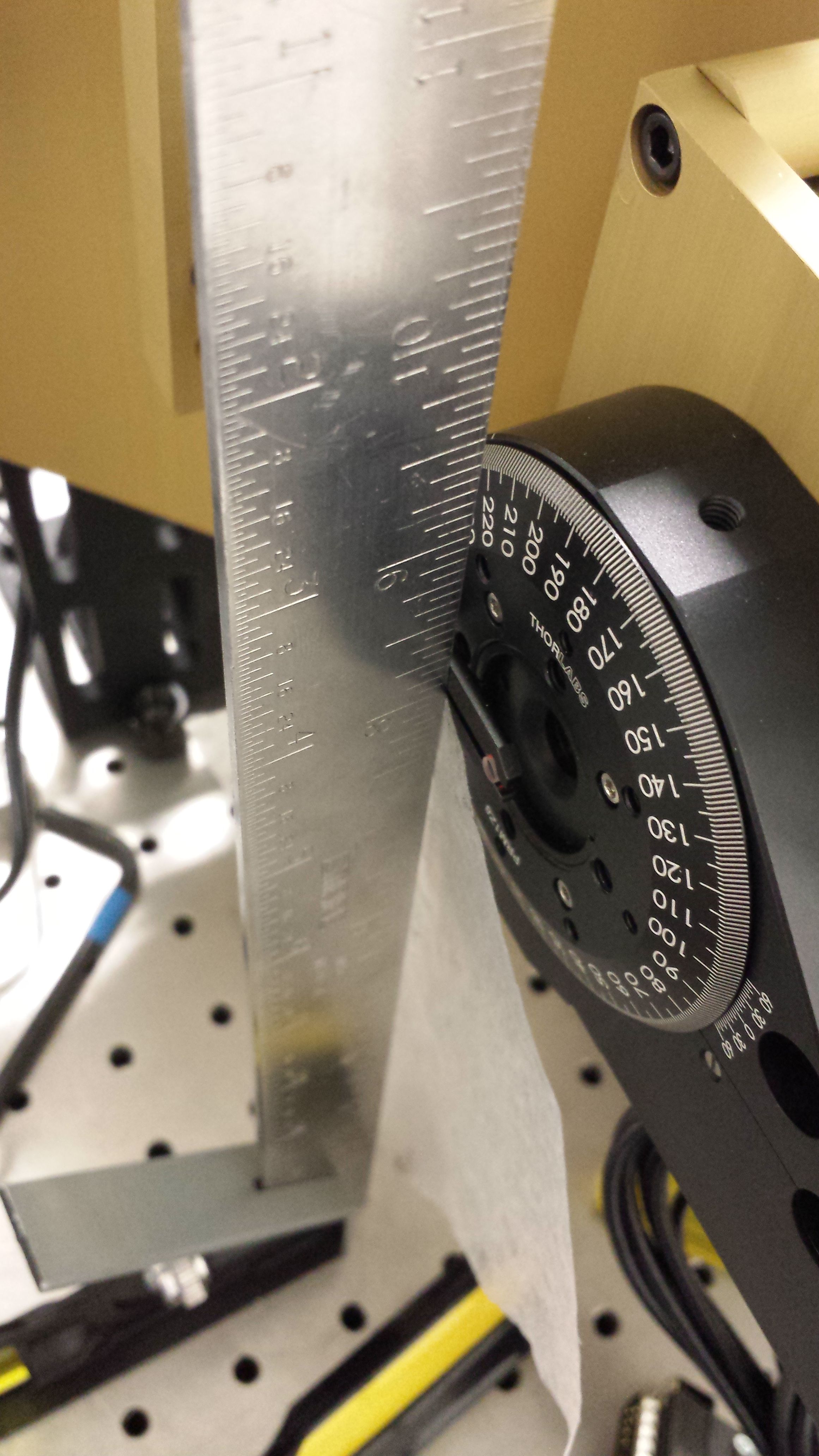
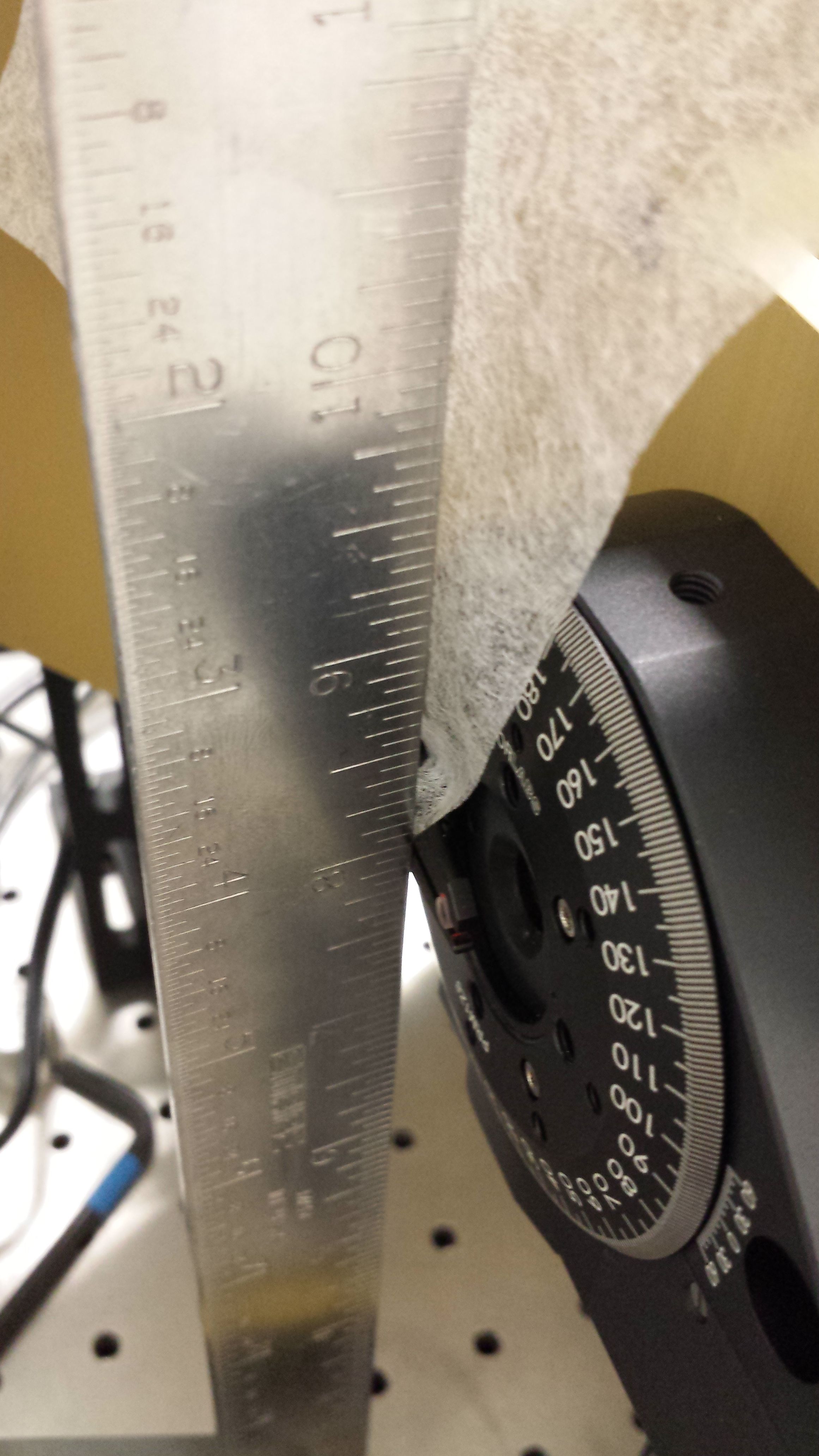
7b. The device has a long arm, and doesn't have the adjustment of fine rotation. The question is how do I know if the collimated lens is parallel to the lenslet array. The method I used is to perfect vertical reference like a ruler, and a piece of very thin paper like lens paper. Then push the ruler against the device and use the paper to feel the friction on the top and bottom part of the touched places. If you feel strong friction on both part, then the lens is placed vertically and parallel to the lenslet array. | 7b. The device has a long arm, and doesn't have the adjustment of fine rotation. The question is how do I know if the collimated lens is parallel to the lenslet array. The method I used is to perfect vertical reference like a ruler, and a piece of very thin paper like lens paper. Then push the ruler against the device and use the paper to feel the friction on the top and bottom part of the touched places. If you feel strong friction on both part, then the lens is placed vertically and parallel to the lenslet array. | ||
[[File: alignment_of_collimated_lens1_2013Oct20. | [[File: alignment_of_collimated_lens1_2013Oct20.jpg]] | ||
[[File: alignment_of_collimated_lens2_2013Oct20. | |||
[[File: alignment_of_collimated_lens2_2013Oct20.jpg]] | |||
Latest revision as of 19:13, 20 October 2013
1. make sure the input collimated beam is parallel to the table:
It is relatively easy to mount the camera parallel to the optical table, so I think it is useful to align the beam parallel to the table too. I also find it is useful to mount the input beam source on a linear stage so that when you align the beam parallel to the table, you can easily move the beam around to shoot it into the camera.
Depending on the detailed setup, the alignment procedure could be different. Usually it is useful to have a mirror or the source that can be steered in tiptilt. Then a common alignment procedure will be to use the tiptilt control to align the same target close to and far away from the beam source. The procedure takes several iteration steps.
2. make sure the home-made front metal panel is perpendicular to the beam.
2a. assemble the metal pieces, no lens or camera.
2b. keep the beam size as small as possible (<~ 1mm)
2c. put in the hole-made cylindrical target into the S mount on front metal panel, and move the beam source to be aligned to
the target. This step can be rough.
2d. install the lens tube with flat mirror (edmund, #45598, #63951) to the S mount on the front metal panel
2e. loose the four screws that tight the metal baseplate to the linear xyz stage (newport ultra 562). Rotate the whole metal piece so that the reflected beam matches the incoming beam
3. align the beam with the camera
3a. attach the camera to the front metal panel
3b. install the first reimaging lens, you should be able to see a spot on the detector. Then loose
the screws on the camera, try to move the camera to put the spot at the center
of the final readout area. the readout size should start with full frame so that you can see where the spot is on the detector. Note: we are in crop mode, so if you see
light in a subarray readout, this doesn't mean the light is really in the subarray area. That's why you want to start out with full frame.
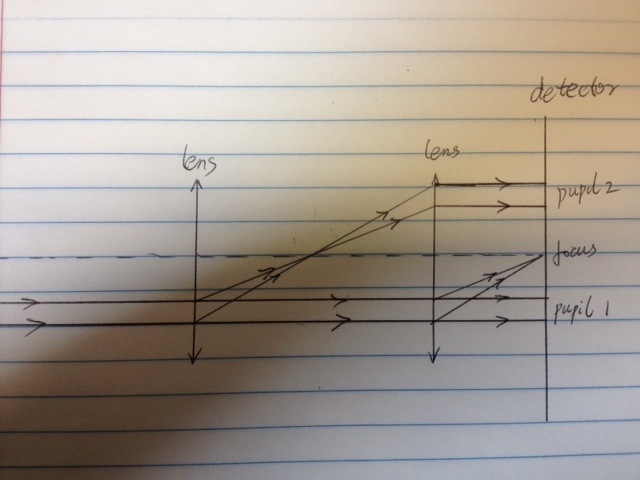
3c. Then take out the lens, you will be see a pupil on the detector. try to move the linear xyz stage of the camera to move the center of the pupil to match
where the spot was.
3d. put on the lens again to check if the spot has moved. If it has moved a little, iterate the above steps to get the spot match the center of the pupil.
Here is my understanding of how this step works.

5. align the reimaging lens pair with the camera.
5a. Then put on the second lens, you will see the pupil again on the detector. The center of the pupil should
be close to the spot (< 5 pixels). If not, there must be some misalignment in the previous steps.
6. align the lenslet array
6a. install the lenslet array, and you should be able to see many spots from the lenslets.
6b. un-tighten the screws holds the rotation stage to move the rotation stage so that the spots-of-interest are not on the edge of the detector readout array. Usually I will keep at least 3 pixels away from the edge.
7. align the collimated lens
7a. The device (optosigma, # 111-1310) that holds the collimated lens is not very secure. It is good enough for lab test, but probably not enough for on sky. So use glue to attach the lens to the optosigma device.
7b. The device has a long arm, and doesn't have the adjustment of fine rotation. The question is how do I know if the collimated lens is parallel to the lenslet array. The method I used is to perfect vertical reference like a ruler, and a piece of very thin paper like lens paper. Then push the ruler against the device and use the paper to feel the friction on the top and bottom part of the touched places. If you feel strong friction on both part, then the lens is placed vertically and parallel to the lenslet array.

